TL;DR – Steps to configure a virtual OT sensor to use for a Defender for IoT POC.
I promised one of my partners that I would document the steps I followed to build my Defender for IoT OT sensor demo instance. I had to build a virtual appliance because (A) I don’t have access to any of the physical appliances and (B) even if I did, I don’t think any of the nearby facilities would allow me to just plug in to their network. So, that’s what I am doing in this post!
My setup and documentation
I am using an Azure VM and within that I create a local Hyper-V VM, because the sensor is an appliance, so it can’t just be an Azure VM on its own. The instructions I followed are really a compilation of steps. I started with the official documentation, which was very helpful, but I also combined with some information from this hands-on-lab. The lab uses the older version 10, but still included some screenshots and information that I thought was helpful. And I also had help from my colleague, Nick, who helped me brainstorm a few issues we hit along the way. Thanks!
Hyper-V Pre-Configuration
The instructions to pre-configure the VM are pretty much straight from the hands-on-lab. I am using a 4×8 because that works great with the Azure VM size I chose. And you’ll see this will map to the Ruggedized sensor option later on. Also, please keep in mind that I am not connecting my sensor to any other management console for this POC.
In my case, my Windows 11 host Ethernet adapter is assigned an IP of 10.7.0.4, therefore I used 192.168.0.0/24 as the network scope of the “NATSwitch”. And I created the two switches as shown below:
New-VMSwitch -SwitchName "NATSwitch" -SwitchType Internal
New-VMSwitch -SwitchName "MySwitch" -SwitchType Internal
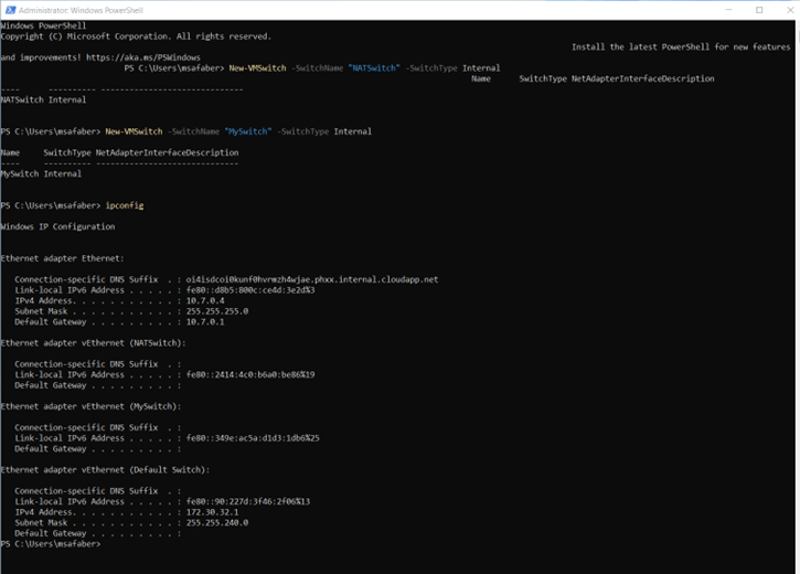
I stored the network adapter information in a variable and then assigned an IP address to the NATSwitch (in my case 192.168.0.1).
$s1 = Get-NetAdapter -name "vEthernet (NATSwitch)"

New-NetIPAddress -IPAddress 192.168.0.1 -PrefixLength 24 -InterfaceIndex $s1.ifIndex

Additionally, you will need to set the IP and DNS on that adapter which can be done manually or by using the following:
Set-NetIPAddress -InterfaceIndex $s1.ifIndex -IPAddress 192.168.0.1 -PrefixLength 24
Set-DnsClientServerAddress -InterfaceIndex $s1.ifIndex -ServerAddresses 8.8.8.8
And I created the new NAT network:
New-NetNat -Name MyNATnetwork -InternalIPInterfaceAddressPrefix 192.168.0.0/24

The final configuration looks like this:

Create new Hyper-V VM
The steps to create the Hyper-V VM are pretty much straight from the documentation. The Hyper-V VM is then created using the image that you download from the portal, as shown below:

And specifically, step 1 of the onboarding process, as shown below.
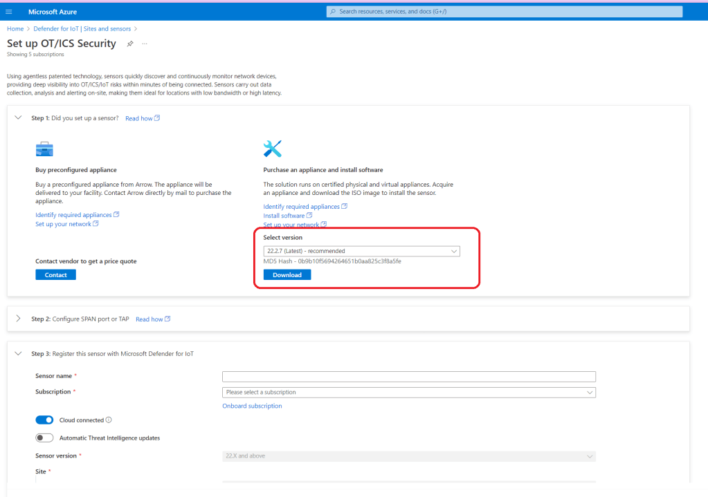
You will use that image file when you create your Hyper-V VM, by selecting Install an operating system from a bootable CD/DVD-ROM within Installation Options and then selecting Image file (.iso), where you use the specific directory where you copied the file to in the Azure VM.
The settings on your Hyper-V VM should end up looking something like this. Please note, I have an extra switch, but you only need two.

Now you can connect to the VM, so you can complete the next steps.
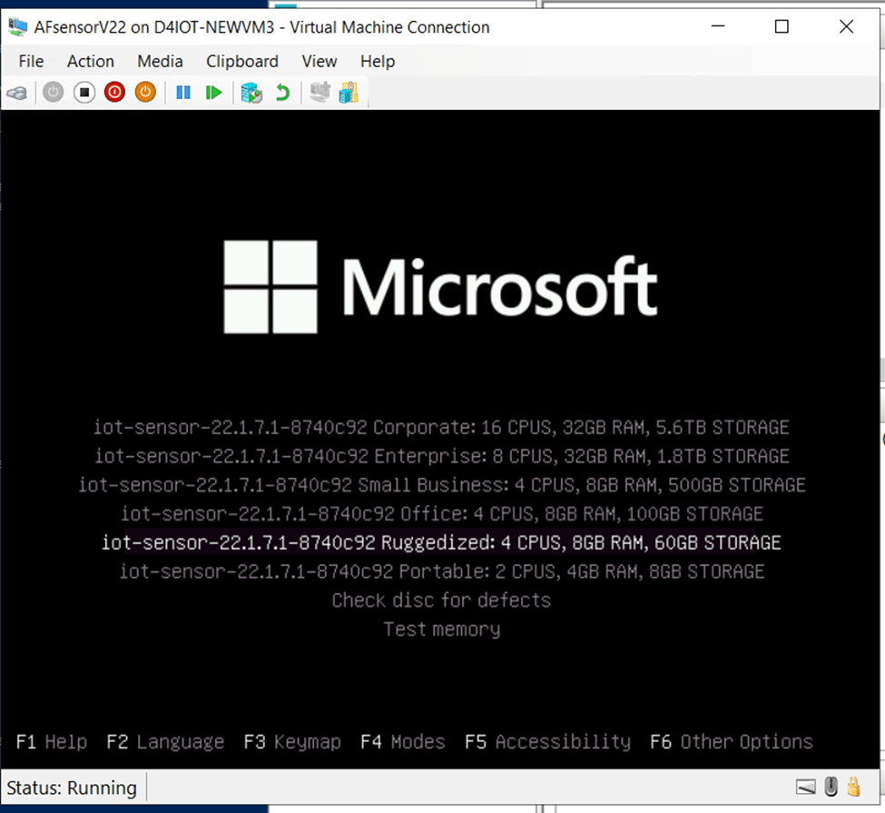
The first screen you will see will give you the option to select a language, after that you will see a selection of installation options. As mentioned earlier, I chose to go with the Ruggedized just based on the size of my POC.
The installation will take a few minutes and then you’ll see the first options to configure your sensor. In my case for the monitor interface, I chose eht1, based on the configuration of my switches.

And I chose eth0 for the management interface.

A few notes on the other options that followed:
- I skipped erspan, this just for Cisco devices.
- I chose 192.168.0.50 for my sensor IP, based on my network configuration above.
- I used the default backup directory.
- I used 255.255.255.0 for subnet mask
- I used 8.8.8.8 for DNS
- I used 192.168.0.1 for gateway IP
- No proxy
And after another few minutes you will see the passwords. Take a picture!! You will not see this again.

Final steps
In order to configure your sensor, you will need to download the registration file that will be generated on step 3 from the portal when you click on “Register“.

Back in the Azure VM, I can now open a new browser session and connect to https://192.168.0.50 (my sensor IP). Please note the first time you connect you can configure a certificate to be used for this connection, or you can just use the default one, which is what I am using and why it shows as Not secure in the browser. Also, the first time you connect you will be required to upload that file you downloaded during the registration process (step 3).
And once that is done you will be able to login with the cyberx user and password from the screenshot you took when the installation was complete.

If you need to connect to the sensor to run CLI commands, you can connect using the support user and password from the screenshot you took when the installation was completed. You can run commands, such as the ones shown below.

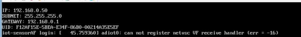
Also, if you see this error when connecting to the host, don’t be concerned. I have this error showing up every time I restart the VM and so far, everything is working as expected.
adiot0: can not register netvsc VF receive handler (err = -16)
A few optional steps
This is my demo instance, so I really don’t have anything connected to monitor. Therefore, I need to gather my data from PCAP files. In order to do that, I first need to make a small update to be able to play those files.
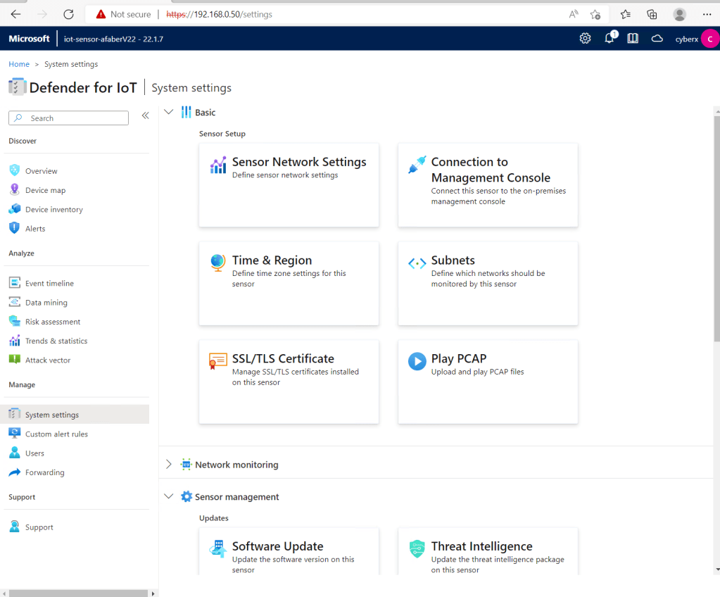
Navigate to System settings, and then select Advanced Configurations:

Select Pcaps from the drop down and then update the settings highlighted below.

This will enable the Play PCAP option shown below.
And now you can begin exploring your findings. You can see the Device map, as shown below.

Alerts

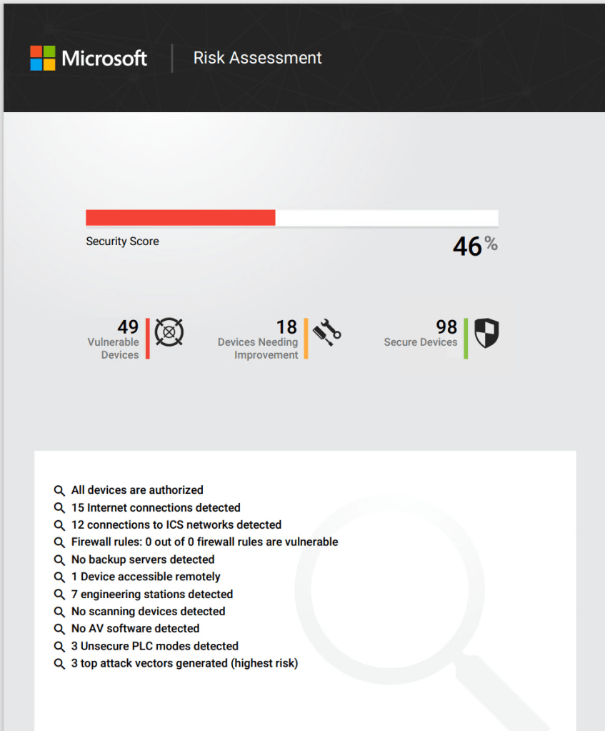
And even generate a detailed Risk Assessment report to provide to your customers.
I hope you take the time to explore this very powerful service. In a future blog post I’ll cover the integration with Microsoft Sentinel and the better together story of how these two services come together to bridge the gap between OT and IT.

Good stuff as always. I cant say i understood fully as its a super complex topic in itself. I did get a very good idea.
LikeLike
Can you tell where to download some good PCAP files for demonstration purposes?
LikeLike
Partners that are working on building Defender for IoT offers can reach out to their CSA directly or via their PTS for some sample files.
LikeLike